Views: 162 Author: Site Editor Publish Time: 2026-09-12 Origin: Site


Energy storage deployment is maturing at a rapid pace globally. We are moving past simple capacity metrics toward rigorous standards for operational efficiency and lifecycle management. As systems scale, uncontrolled battery heat dissipation quickly becomes a critical liability. High temperatures trigger accelerated cell degradation and severe thermal runaway risks. Furthermore, inefficient cooling creates parasitic loads that drain system profitability.
We developed this transparent, engineering-focused comparison to help you navigate these complex design challenges. Technical buyers and project developers need clear, actionable data to make informed choices. You will discover how to align your system architecture with both commercial targets and operational constraints. Choosing the right configuration determines long-term reliability. We will break down the exact performance trade-offs you must consider to protect your next major storage investment.
The choice between cooling architectures directly dictates system footprint, OPEX, and lifecycle cell degradation.
Air cooling prioritizes system simplicity, lower initial CAPEX, and ease of maintenance, best suited for low C-rate applications and temperate climates.
Liquid cooling excels in thermal uniformity and spatial density, making it mandatory for high-capacity, high C-rate (1C+) utility-scale projects.
Total Cost of Ownership (TCO) models must factor in parasitic load (HVAC vs. pump efficiency) and maintenance complexity over a 10-to-15-year lifecycle.
We must evaluate cooling as a core profitability driver. Effective BESS thermal management dictates overall round-trip efficiency. We measure this efficiency through the Coefficient of Performance (COP). A higher COP means the cooling mechanism consumes less energy to remove heat. This directly reduces the parasitic load on your battery system. When a cooling system draws heavy power from the grid or the battery, it reduces the net energy available for dispatch. Optimizing COP protects your revenue stream.
Next, you must consider lifecycle degradation. Temperature uniformity plays a critical role here. Engineers measure this uniformity as the delta T (ΔT) across cell racks. Lithium-ion cells operate best between 20°C and 25°C. When ΔT widens, certain cells age much faster than others. The Battery Management System (BMS) will eventually limit the entire rack based on these degraded cells. This uneven aging accelerates capacity fade. It drastically reduces the usable life of the entire system.
Finally, robust cooling ensures risk mitigation and compliance. Poor heat removal invites thermal propagation. If one cell fails, excess heat can trigger neighboring cells into thermal runaway. Modern fire safety codes, such as NFPA 855, require strict safeguards against this cascading failure. Efficient cooling architectures form the first line of defense against catastrophic thermal events. They help project developers secure permits and negotiate favorable insurance premiums.
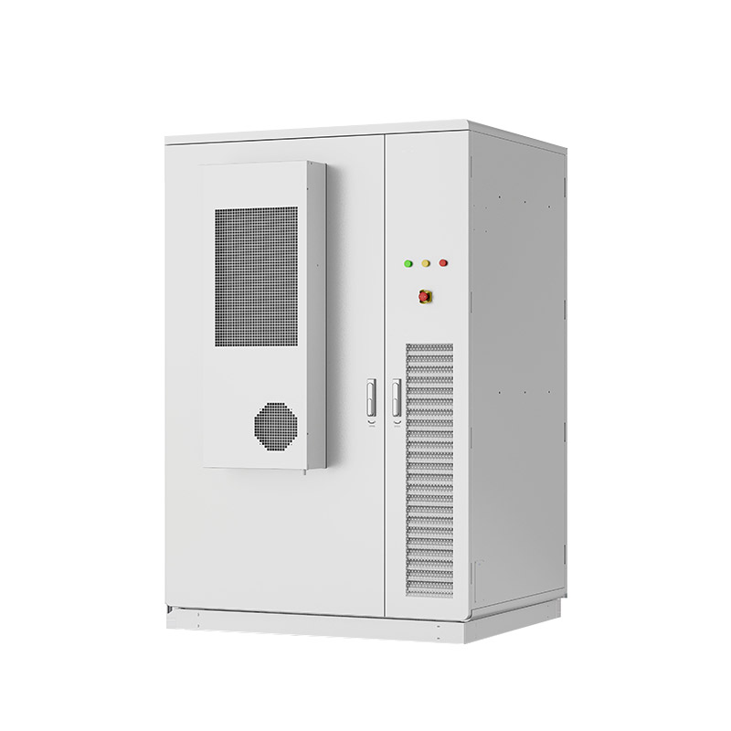
Let us examine the traditional air cooled energy storage system. This architecture relies on proven, conventional mechanical concepts. It utilizes HVAC units, industrial fans, and strategic ducting. The system pushes chilled air across battery racks to remove heat via convective heat transfer. Air flows through engineered pathways between battery modules. Warm air then exhausts out of the container or returns to the HVAC unit for recirculation.
Air cooling offers several distinct benefits for specific project types. The system architecture provides simplified installation. It features fewer moving parts at the module level. You deal with fans and compressors rather than complex fluid networks.
Lower upfront CAPEX: Standardized HVAC components keep initial equipment costs low.
Component availability: You can easily source replacement fans and filters from local suppliers.
Zero liquid risk: This design eliminates the risk of liquid leaks damaging sensitive electrical components.
Despite its simplicity, air cooling presents significant engineering trade-offs. The most prominent issue involves uneven temperature distribution. Cells positioned near the chilled air intake stay cool. Cells located near the exhaust absorb the accumulated heat. This creates a higher ΔT across the system.
Additionally, you face higher parasitic power consumption in extreme ambient temperatures. When outside temperatures soar, HVAC compressors must work continuously. This heavy fan usage drains system efficiency. You also need a larger physical footprint. The container requires substantial empty space to accommodate bulky airflow pathways and ducting.
We recommend air-cooled architectures for specific applications. They perform best at C-rates below 0.5C, where heat generation remains moderate. They suit smaller commercial and industrial (C&I) deployments perfectly. Furthermore, installations in mild, consistent climates benefit greatly from this straightforward approach. If you do not require aggressive cycling, air cooling delivers a reliable, cost-effective solution.
Now we turn to liquid-cooled configurations. This system circulates a specialized coolant, typically a water-glycol mixture. The fluid flows through a liquid cold plate module. Engineers integrate this plate directly with or adjacent to the battery cells. Heat transfers conductively from the hot cell to the cold plate. The fluid then carries the heat away to an external chiller unit.
Liquid cooling provides unmatched thermal control. Liquids possess a superior specific heat capacity compared to air. They absorb and transport heat much more efficiently. This enables precise temperature regulation.
Tight thermal uniformity: Liquid systems often maintain a cell-to-cell ΔT of less than 3°C.
High energy density: Removing bulky air ducts allows for highly compacted container designs. This significantly reduces your required land footprint.
Lower parasitic load: Efficient pump circulation consumes less power than heavy HVAC fan usage during peak operations.
These performance benefits come with increased complexity and cost. You face a higher upfront CAPEX. Liquid systems typically cost 15% to 25% more during initial installation. You must invest in specialized cold plates, pumps, and manifolds.
Furthermore, complex plumbing introduces potential failure points. Coolant leaks inside a battery rack can cause catastrophic short circuits if safety mechanisms fail. You also require specialized maintenance protocols. Technicians must perform routine coolant flushing, check fluid pH levels, and maintain leak detection sensors.
Liquid cooling stands as the mandatory choice for demanding applications. We specify it for large utility-scale projects. It handles high C-rate applications (1C to 2C+) effortlessly. If your project involves frequency regulation or rapid charging cycles, you need liquid cooling. It also thrives in harsh or highly variable climates where air systems struggle to keep up.
Choosing between an air cooled vs liquid cooled BESS requires a detailed matrix evaluation. We must compare footprint, cell lifespan, financial overlap, and safety paradigms.
First, look at spatial density. Liquid cooling achieves up to 30% to 40% higher density (MW/MWh per square meter). Air systems need wide aisles for airflow. Liquid systems pack cells tightly together. This difference matters greatly when land costs are high.
Next, analyze thermal uniformity. We established earlier that air-cooled systems suffer from uneven aging. Over a 10-year span, this uneven aging forces premature rack replacements. Liquid-cooled systems promote balanced aging. They protect your capacity yield over the long term.
You must also chart the CAPEX vs. OPEX overlap. Liquid cooling costs more upfront. However, its lower parasitic energy costs eventually offset the initial capital penalty. The breakeven point usually occurs between years three and five, depending on local electricity rates and duty cycles.
Finally, contrast the safety paradigms. Air-cooled systems rely on rapid exhaust venting and gaseous fire suppression. Liquid systems focus on rapid leak detection and fluid isolation. Many modern liquid systems utilize negative pressure designs. If a hose breaches, the system sucks air in rather than spraying coolant out.
Table 1: Thermal Architecture Evaluation Matrix
Evaluation Metric | Air-Cooled System | Liquid-Cooled System |
|---|---|---|
Spatial Density | Moderate (Requires air ducts) | High (30-40% denser layout) |
Temperature Uniformity (ΔT) | Typically 5°C - 8°C | Consistently < 3°C |
Upfront CAPEX | Lower Baseline Cost | 15% - 25% Premium |
Parasitic Load (Peak) | High (Heavy HVAC fan draw) | Low (Efficient pump circulation) |
Maintenance Complexity | Low (Filters, belts, fans) | High (Coolant flushes, leak sensors) |
Theoretical benefits mean little without practical execution. You must prepare for specific rollout risks and maintenance realities for each architecture.
Air-Cooled Commissioning: You will face ductwork balancing challenges. Technicians must conduct thorough airflow validation. They use anemometers to ensure air reaches the furthest racks. Improper baffling leads to immediate hot spots.
Liquid-Cooled Commissioning: You face pressure testing and fluid dynamics challenges. Technicians must purge all trapped air from the coolant loops. They perform rigorous hydrostatic pressure tests before introducing the water-glycol mix. A single loose fitting delays the entire project.
Maintenance routines differ drastically. Air system maintenance feels familiar to standard facility teams. You change air filters quarterly. You inspect compressor belts and clear debris from exterior condenser fins. It requires minimal specialized training.
Liquid system maintenance requires specific expertise. Technicians must check coolant degradation. Glycol breaks down over time and loses its anti-corrosive properties. You must sample the fluid annually. You also monitor pump health, verify valve integrity, and test the leak detection alarms.
You must plan for distinct failure modes. A catastrophic fan failure in an air-cooled unit results in a gradual heat rise. The BMS detects the rising temperature and slowly derates the system. You have time to react.
A catastrophic pump failure or major hose leak in a liquid system triggers an immediate system trip. If coolant breaches the battery trays, it causes localized damage. You must maintain critical spare parts on-site to minimize downtime from these immediate trips.
You need a structured decision framework to select the ideal energy storage cooling system. Follow these actionable steps to align your engineering needs with commercial realities.
Start by defining your hard constraints. What is your required C-rate? If you plan to operate above 1C, you should eliminate air cooling immediately. Next, determine your maximum allowable footprint. Tight urban sites often dictate liquid cooling by default. Finally, analyze ambient climate data. High-temperature regions require the heavy-duty heat removal capabilities of liquid systems.
Run a comprehensive 10-year financial model. Do not simply look at the purchase order. You must factor in local energy costs for parasitic loads. Calculate how much power the HVAC fans will consume during peak summer months. Compare this against the steady, lower power draw of liquid pumps. Model the revenue lost to capacity degradation over the decade. This exercise reveals the true operational cost of the thermal architecture.
Interrogate your Original Equipment Manufacturers (OEMs). Ask specific questions regarding the mean time between failures (MTBF) for critical cooling components. Request detailed warranty stipulations tied to temperature variance. Will the OEM void the battery warranty if the ΔT exceeds a certain threshold? Finally, verify their localized support capabilities. If a fluid pump fails, you need to know how fast they can deploy a specialized technician to your site.
Neither cooling technology serves as a universally superior choice. The optimal thermal architecture relies heavily on your specific duty cycle, site constraints, and long-term financial modeling. Air cooling offers undeniable simplicity and cost-effectiveness for steady, low-demand applications. Liquid cooling provides the dense, high-performance thermal control required for aggressive utility-scale operations.
To ensure project success, take the following actions:
Prioritize rigorous lifecycle financial modeling over raw initial CAPEX comparisons.
Map your required C-rate and environmental climate data before selecting a container design.
Ensure your maintenance teams possess the correct training for the chosen technology.
Demand strict warranty guarantees from OEMs regarding temperature uniformity across the battery racks.
A: Liquid-cooled systems typically maintain a very tight temperature difference of less than 3°C across all battery cells. Air-cooled systems generally experience a wider variance, usually between 5°C and 8°C. This happens because air absorbs heat progressively as it travels down the ducting pathways.
A: While introducing liquids near electronics poses inherent risks, modern designs mitigate this effectively. Manufacturers use specialized coolants and negative pressure system designs. If a leak occurs, the system draws air in rather than spraying liquid out. Advanced leak detection safeguards also shut down the system instantly to prevent electrical shorts.
A: Liquid cooling generally consumes less parasitic power. Liquids have a much higher heat capacity than air. It takes significantly less energy to circulate fluid via a pump than it does to force massive volumes of air through restrictive ductwork using heavy HVAC fans. This improves overall system round-trip efficiency.
A: No, retrofitting is generally not viable. The two systems utilize fundamentally different rack designs, spacing requirements, and container architectures. Liquid systems require integrated manifolds and cold plates built directly into the battery modules. You must choose your cooling architecture definitively during the initial project design phase.


