Views: 0 Author: Site Editor Publish Time: 2026-10-21 Origin: Site


Are unexplained power losses ruining your newly commissioned battery setup? You are not alone. Designing a high-capacity energy storage system only to find it underperforming during peak loads is a frustrating reality. Voltage drop acts as a silent killer in energy storage. Engineers often spend weeks debating battery cell chemistry and inverter specifications. Meanwhile, the physical routing of the electrical infrastructure is frequently ignored. Poor wiring layout is usually the actual hidden culprit behind sluggish performance and phantom energy drains.
In this practical guide, we will explore the exact science behind these inefficiencies. We will break down how layout dictates resistance and why improper topologies accelerate battery degradation. We will also show how utilizing a strategically designed custom energy storage wiring harness permanently solves these engineering challenges.
Layout Dictates Resistance: Physical routing, length, and topology directly impact total circuit resistance and subsequent voltage drop.
Voltage Drop Equals Power Loss: Even a seemingly minor 2 to 3 percent drop triggers active power losses, uneven cell charging, and thermal runaway risks.
BMS Accuracy Relies on Wiring: A properly laid out management harness is critical. Without it, voltage sensing and cell balancing become dangerously inaccurate.
High-Voltage Demands Precision: Grid-scale and EV fast-charging systems require meticulously designed assemblies to handle massive current loads safely.
Customization is Key: Off-the-shelf cables force inefficient routing. Custom solutions ensure exact lengths, slashing resistance and maximizing system ROI.
To understand how spatial arrangement affects system performance, we must first examine the basic physics governing electrical circuits. Voltage drop is calculated using Ohm’s Law. Simply put, Voltage Drop equals Current multiplied by Resistance. In high-capacity Battery Storage Systems, the current can be exceptionally high. Consequently, even a microscopic amount of resistance in the conductors will result in a measurable loss of voltage.
Several inherent factors contribute to this resistance before the physical arrangement is even considered. Every conductor possesses natural electrical resistance. Copper remains the gold standard due to its superior conductivity. Aluminum is sometimes substituted to cut costs, but it introduces higher resistance. Furthermore, the wire gauge dictates how much current can flow without restriction. Smaller cross-sectional areas present a tighter bottleneck.
Temperature also introduces a volatile variable into this equation. As the internal temperature of a conductor rises, its electrical resistance climbs concurrently. Picture a densely packed commercial battery cabinet where cables are bundled tightly together. If the layout restricts airflow, normal current flow generates trapped heat. This heat increases the resistance, which in turn generates more heat. This compounding negative loop severely impacts the efficiency and safety of the entire installation.
While you cannot rewrite the laws of physics, system integrators wield complete control over the mechanical layout of the wiring. The spatial arrangement of the internal cabling is arguably the most critical factor in minimizing unnecessary ohmic resistance.
Excessive cable length is the biggest layout mistake. Copper has inherent resistance. Every extra inch adds ohmic loss. Installers often route cables through unnecessarily long paths, looping them around racks just to make the installation look neat. This is a critical error. When routing paths are not optimized for the absolute shortest distance between battery terminals and the inverter, the cumulative voltage drop across a megawatt-scale system easily exceeds acceptable operational thresholds.
The topology of the battery connections dictates exactly how voltage drop is distributed across the battery bank. Connecting batteries in a long daisy-chain series or parallel layout is a common but fundamentally flawed practice. In a daisy-chain setup, the current from the furthest battery must travel through the connections and cables of all preceding modules. As a result, the batteries at the far end of the line experience a significantly higher voltage drop than those positioned closest to the load.
In contrast, routing cables from each battery to a centralized busbar equalizes the cable lengths. This structural choice, known as a star topology, ensures uniform voltage drop across the entire system. It allows all battery modules to operate under identical electrical conditions.
Feature | Daisy-Chain Topology | Star Busbar Topology |
|---|---|---|
Cable Lengths | Variable, increases down the line | Equalized for all modules |
Voltage Drop | Uneven, highest at the end of the chain | Uniform across the system |
Thermal Load | Concentrated on primary connection points | Distributed evenly across all lines |
System Efficiency | Lower due to series resistance buildup | Higher through optimized parallel flow |
A continuous copper wire has a highly predictable resistance profile. However, every time that wire is cut, crimped, or bolted to a terminal, localized contact resistance is introduced. A layout requiring multiple splices, transition points, or intermediate connectors inherently suffers from higher voltage drops than a continuous run. Minimizing the number of physical connection points through strategic layout planning is essential for maintaining optimal conductivity.
Voltage drop is not merely a theoretical number on a multimeter. It carries severe, tangible consequences for the operational efficiency and lifecycle of your energy storage investment.
When a voltage drop occurs between the battery bank and the inverter, the inverter receives less voltage than the cells are actually producing. To maintain the required power output, the inverter must draw more current to compensate for the sagging voltage. This dynamic leads to active power losses, generating excess heat and noticeably reducing the round-trip efficiency of the energy storage system.
Layout-induced voltage drop triggers uneven cell charging and discharging. If the voltage drop varies between different racks due to unequal cable lengths, the inverter perceives the batteries as having different states of charge. Consequently, batteries connected via shorter cables will charge and discharge at much faster rates than those shackled by longer cables.
This uneven cycling forces specific cells to work significantly harder than their counterparts. The overworked cells experience localized heating and accelerated chemical degradation. Over time, this imbalance destroys the usable capacity of the entire system. It severely shortens the overall lifespan of the battery bank, effectively ruining the projected return on investment.
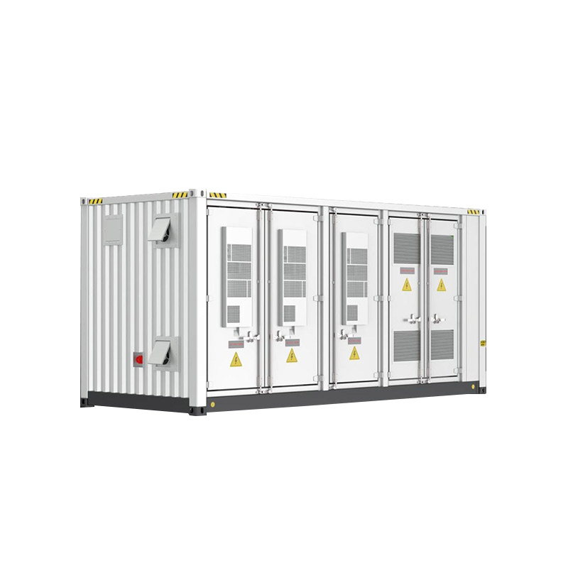
Recent engineering data highlights a definitive shift in battery energy storage architectures toward higher DC bus voltages. Developers are rapidly migrating from standard 400V or 800V architectures up to 1500V systems. This transition is primarily driven by utility-scale containerized air-cooled BESS units pushing massive capacities like 3.44MWh. The goal is to reduce current levels for the same power output, which theoretically minimizes ohmic losses and allows for thinner cables.
However, scaling up the voltage introduces severe layout complexities. At 1500V, the spatial requirements for arc fault mitigation are strict. Combined with the sheer rigidity of thicker, cross-linked insulation required to handle extreme operating temperatures from minus 30 degrees Celsius to 55 degrees Celsius, traditional field-routing methods are now obsolete. The industry is moving decisively away from field-assembled cabling. Precisely engineered, factory-tested custom harnesses are the new standard. As power density increases, mechanical layout and electrical performance become inextricably linked. There is simply no room for installation guesswork.
Mitigating voltage drop requires a proactive approach to mechanical and electrical design. Engineers must prioritize spatial optimization from the earliest stages of system development, rather than treating wiring as an afterthought. Here are the specific parameters you must enforce.
Designing the physical enclosure to keep the inverter and main DC busbars as close to the battery terminals as physically possible is the crucial first step. More importantly, engineers must strictly adhere to the Equal Resistance Rule. When designing the layout for parallel battery strings, ensure that the cables running from each string to the common busbar are exactly the same length down to the millimeter. Even if a battery module is positioned right next to the busbar, its cable should match the length of the furthest battery. This counterintuitive practice perfectly balances the resistance and equalizes the voltage drop across all strings.
High-current DC cables generate substantial electromagnetic fields. If low-voltage communication cables are routed parallel to and touching these main power lines, electromagnetic interference occurs. This interference distorts the digital signals passing to the system controller. A strategic layout enforces strict physical separation between high-current power cables and communication lines to maintain signal integrity and prevent erratic system behavior.
Routing cables through tight corners to save space is a critical installation error. Sharp bends in a layout stress and fracture the internal copper strands of the cable. Damaged strands reduce the effective cross-sectional area of the wire. This instantly increases localized resistance and creates dangerous hot spots. Layouts must respect the minimum bend radius specified by the manufacturer to ensure long-term structural and electrical integrity.
The BMS wiring harness acts as the central nervous system of any energy storage unit. Its primary function is to constantly monitor voltage and temperature at the individual cell and module levels, transmitting this critical data back to the central controller.
The physical layout of the main power cables directly impacts the accuracy of the battery management system. If the main power cables suffer from a high voltage drop due to poor layout, the voltage measured at the inverter will be noticeably lower than the voltage generated at the cell terminals.
Specifically, if the management harness itself is improperly routed, it transmits false readings. Exposure to electromagnetic interference from unshielded power cables or excessive cable length will corrupt the data. When the system receives inaccurate voltage data, it may prematurely halt the charging process, falsely assuming the cells are full. Conversely, it might stop the discharging process early, assuming the cells are depleted. This layout failure effectively reduces the usable capacity of the battery and prevents the system from operating at its full potential.
As the energy sector moves toward larger grid-scale energy storage and electric vehicle fast-charging infrastructure, system voltages frequently exceed 1000V DC. Operating under these extreme electrical stresses fundamentally changes the layout requirements.
Laying out a high-voltage battery cable assembly requires strict adherence to advanced engineering protocols. At 1000V and above, the risk of electrical arcing and severe thermal events increases exponentially. Layouts must incorporate specific physical spacing between positive and negative conductors to prevent dielectric breakdown. The cables themselves must feature heavy-duty, cross-linked insulation, typically rated UL94 V-0 flame retardant, to withstand ambient heat and prevent micro-arcing over a 10000 plus cycle life.
Beyond this, layout planning at a grid scale is heavily regulated by safety and compliance standards like UL 9540 and IEC 62619. These regulations dictate minimum bend radii, wire support mechanisms, and thermal management strategies to mitigate thermal runaway risks. A layout that fails to accommodate the physical bulk and rigidity of high-voltage assemblies will fail compliance testing and pose a severe safety hazard to operators.
Even with a solid theoretical understanding of voltage drop, system integrators often make practical errors during the installation phase that compromise the entire layout.
One of the most prevalent mistakes is using off-the-shelf cables. Installers often purchase pre-made cables that are slightly longer than necessary. Instead of cutting them to size, they coil the excess cable inside the cabinet to avoid re-crimping heavy-duty terminals. Coiling high-current DC cables creates an unintended inductor. This introduces electrical noise and significantly increases the total resistance and voltage drop.
Inconsistent terminal torquing is another frequent error. If the layout is cramped, installers struggle to apply the correct torque to terminal bolts. Loose connections act as high-resistance bottlenecks, causing massive localized voltage drops and generating enough heat to melt terminal blocks entirely.
Ignoring environmental factors during layout planning can be disastrous. Routing harnesses through areas of the cabinet with poor ventilation, or directly above heat-generating components like inverters, exacerbates heat-induced voltage drop. Conductors must be routed through designated, thermally managed channels to maintain optimal conductivity.
Attempting to force standard, mass-produced cables into a complex battery storage architecture almost always results in compromised routing, unequal cable lengths, and unacceptable voltage drop. The only definitive way to perfectly optimize a layout and eliminate unnecessary resistance is through precise customization.
A custom wiring solution is manufactured to exact length specifications based on your specific cabinet CAD drawings. This precision engineering eliminates excess cable slack, prevents dangerous coiling, and ensures perfectly balanced lengths for parallel strings, directly satisfying the Equal Resistance Rule.
In addition to exact lengths, custom solutions allow engineers to specify tailored components. You can dictate the exact wire gauge, select heavy-duty IP67 waterproof terminal lugs, and demand precise high-temperature insulation required for your system's unique topology and voltage rating.
While custom engineering requires a slightly higher initial capital expenditure compared to bulk commercial cables, the return on investment is undeniable. The upfront cost is quickly dwarfed by the long-term savings achieved through maximized system efficiency, minimized active power loss, and the extended lifespan of the battery modules due to perfectly balanced cell cycling.
Voltage drop is not just a minor inconvenience. It is a critical system efficiency metric dictated heavily by wiring layout, cable length, and topology. When energy storage systems fail to meet their output projections, the physical electrical pathways are often to blame.
Meticulously planning your power cable layout is absolutely necessary for maintaining optimal performance and safety. A precisely routed management harness prevents inaccurate voltage readings, ensuring your battery cells remain perfectly balanced over thousands of cycles. Never compromise system safety or efficiency by forcing generic, off-the-shelf cables into a high-performance environment.
Stop leaving energy on the table. Contact our engineering team at Run Strategy for expert manufacturing and layout consultation. Let us build custom energy storage solutions tailored exactly to your specific architecture and operational demands.
Generally, a voltage drop of less than 2 to 3 percent is considered acceptable for the main direct current runs in most standard residential or commercial installations. However, for high-performance, grid-scale systems, engineers strictly aim for a voltage drop of less than 1 percent. Keeping the voltage drop as low as possible ensures maximum inverter efficiency and minimizes thermal losses during high-current charge and discharge cycles.
Custom harnesses are engineered and cut to the exact lengths required by your specific physical layout. This precision eliminates the excess cable slack and dangerous coiling typically found when using off-the-shelf options. Because electrical resistance is directly proportional to wire length, removing unnecessary length directly reduces the total resistance of the circuit. Custom harnesses also ensure that parallel connections are perfectly balanced, preventing uneven voltage drops across different battery racks.
Yes, it can cause significant long-term damage. The management harness is responsible for transmitting critical cell-level voltage and temperature data to the central controller. If the layout exposes these low-voltage lines to electromagnetic interference from high-power cables, or if the harness is too long and suffers its own voltage drop, the system receives inaccurate readings. This causes the management system to fail in balancing the cells properly, leading to chronic overcharging or over-discharging, which permanently degrades battery chemistry.
Daisy-chaining connects battery modules in a continuous line, meaning the physical distance from the inverter to the last battery is much longer than to the first. This creates unequal resistance and uneven voltage drops, causing the closest batteries to work harder and degrade faster. A star topology routes equal-length cables from each individual battery module to a central busbar. This ensures uniform resistance, meaning all batteries experience the exact same voltage drop and charge or discharge at a perfectly synchronized rate.
High-voltage assemblies are specifically engineered to manage the extreme electrical and thermal stresses of modern energy storage and EV infrastructure, which often operate at or above 1000V DC. Unlike standard wiring, these assemblies utilize thicker, highly specialized cross-linked insulation to prevent high-voltage arcing. They also incorporate advanced shielding against electromagnetic interference and utilize heavy-duty, precisely crimped connectors designed to safely handle massive, continuous current loads without overheating.
Calculating the correct wire size involves knowing the maximum continuous current, the total length of the cable run, and the acceptable voltage drop percentage, usually under 1 percent for commercial systems. Engineers use standardized wire gauge tables and Ohm's Law to determine the required cross-sectional area. For high-capacity systems, upgrading to a larger cable, such as moving from 50 square millimeters to 70 square millimeters, significantly reduces resistance and mitigates heat generation during peak loads.
Absolutely. Copper conductors have a positive temperature coefficient, meaning their electrical resistance increases as they get hotter. If battery cables are routed through poorly ventilated areas or bundled tightly together without proper spacing, the trapped heat will increase the cable's resistance. This higher resistance causes a larger voltage drop and generates even more heat, creating a dangerous thermal cycle that degrades system efficiency and creates fire hazards.


