
Views: 0 Author: Site Editor Publish Time: 2026-10-18 Origin: Site


The global transition toward renewable energy has driven an unprecedented demand for high-capacity battery systems. Facilities increasingly rely on these massive assets for peak shaving, load shifting, and grid stabilization. Consequently, the physical architecture of the battery cabinet has become a major focal point for engineering and safety teams. Among the most critical challenges in operating these high-density systems is thermal management.
Specifically, operators must address the formation of hot spots. These are localized areas of elevated temperature inside battery cabinets that directly threaten system safety, operational efficiency, and overall asset lifespan.
Traditional cooling methodologies served as the industry standard for years. However, empirical field data indicates they consistently struggle to maintain uniform temperatures across densely packed lithium-ion cells. When temperature uniformity fails, financial and safety risks escalate rapidly. Advanced liquid cooling technology has emerged as a highly effective, non-negotiable solution for preventing these dangerous thermal gradients. This article explores the fundamental root causes of hot spots within battery cabinets, compares legacy cooling technologies with modern alternatives, and explains how precision liquid cooling components protect large-scale energy storage investments.
Key Takeaways
Hot spots in battery cabinets stem primarily from uneven internal cell resistance, increasingly dense cell packaging, and the inherent physical limitations of inadequate airflow.
Unchecked thermal gradients lead to accelerated battery chemistry degradation, permanent capacity fade, and catastrophic thermal runaway.
Traditional air cooling is frequently insufficient for modern high-density energy storage systems. It simply cannot cool individual cells uniformly across a large spatial footprint.
A high-quality thermal management architecture utilizing liquid coolants provides direct, highly efficient heat dissipation exactly where it is generated.
The cold plate serves as the primary thermal interface. It physically contacts the battery cells to absorb and remove heat, thereby ensuring strict temperature uniformity.
Proper system design effectively mitigates the common risks associated with liquid cooling, such as condensation, ensuring long-term operational reliability.
To master the mechanics of thermal management, we must first clearly define a hot spot within the specific context of a lithium-ion battery cabinet. Picture a localized physical area within a battery module or rack where the temperature significantly exceeds the average temperature of the surrounding cells. In a well-regulated system, the thermal environment remains homogenous. In a compromised setup, dangerous thermal gradients emerge rapidly.
Lithium-ion batteries naturally generate heat during both charging and discharging cycles. This generation is primarily driven by Joule heating—often called ohmic heat—and exothermic chemical reactions occurring deep within the cell core. As charge and discharge rates increase to meet aggressive facility demands, electrical current spikes. This causes a proportional, often sharp, rise in heat generation.
During normal operation, this thermal energy must be continuously and evenly extracted from the cabinet. If the heat removal mechanism is inefficient, energy accumulates in specific pockets. This raises the localized temperature and births a hot spot.
In industrial applications, absolute temperature is only half the battle. Temperature uniformity is equally critical. Battery manufacturers generally specify that lithium-ion cells operate most efficiently and safely between 15°C and 25°C. More importantly, the temperature difference across an entire battery module must be maintained strictly below 3°C to 5°C. A cell operating at 30°C while its neighbor sits at 22°C creates a severe electrical imbalance. This forces the cells to age at different rates, fundamentally compromising the electrical harmony of the entire string.
Identifying the root causes of uneven temperature distribution is essential for facility managers evaluating their thermal infrastructure. Imagine a scorching July afternoon at a grid-tied solar farm. The battery containers absorb intense solar radiation while simultaneously dispatching peak power to the grid. Inside, cells packed tightly into racks generate immense ohmic heat. In such scenarios, hot spots rarely stem from a single failure. They are the result of compounding physical and environmental factors.
Despite rigorous quality control during manufacturing, no two lithium-ion cells are perfectly identical. Microscopic variations in electrode coating thickness and internal assembly lead to slight differences in impedance. Under the exact same electrical load, a cell with marginally higher internal resistance will generate more Joule heating than its neighbors. Over thousands of charge cycles, this inherent manufacturing variance causes specific cells to run naturally hotter. These cells act as the genesis point for localized hot spots.
Furthermore, the energy storage industry is constantly pushing for higher volumetric energy density. Engineers are packing more megawatt-hours into standard container footprints. To achieve this, battery cells are squeezed together with minimal spacing. While this maximizes power output per square meter, it drastically reduces the available spatial volume for natural convective heat dissipation. Tightly packed prismatic or cylindrical cells create severe thermal bottlenecks where heat becomes trapped deep within the core of the module.
Recent market analysis highlights a massive shift in grid-scale energy storage trends. The rapid migration from standard 280Ah cells to massive 314Ah and upcoming 500Ah formats has completely rewritten thermal design rules. Industry data reveals that heat flux densities are now exceeding 50kW per rack in high-C-rate applications. At these extreme densities, traditional HVAC systems simply choke. The parasitic load required to run massive fans completely negates the efficiency gains of the larger batteries, forcing the industry to abandon air cooling for utility-scale deployments entirely.
For stakeholders evaluating infrastructure investments, thermal management cannot be viewed merely as a technical specification. It is directly tied to financial returns, operational uptime, and site safety. The consequences of ignoring thermal imbalances in Commercial and Industrial Energy Storage systems are severe and highly measurable.
Lithium-ion battery degradation is heavily dependent on temperature. Following the principles of the Arrhenius equation, chemical reaction rates increase exponentially with heat. In practical terms, for every 10°C increase in operating temperature above the optimal baseline, the lifespan of a lithium-ion cell is roughly halved. When a hot spot subjects a localized group of cells to constant elevated temperatures, the Solid Electrolyte Interphase layer within those cells thickens prematurely. Because battery cells are wired in series to create high-voltage strings, the overall capacity of the entire string is dictated entirely by its weakest, most degraded cell.
Beyond capacity fade, the most catastrophic consequence of a hot spot is thermal runaway. If a localized area reaches a critical temperature threshold—often between 130°C and 150°C—the internal separator dividing the anode and cathode can melt. This triggers an internal short circuit. Massive amounts of stored electrical energy are released as heat in a fraction of a second. The process quickly becomes a self-sustaining, uncontrollable chain reaction that spreads to adjacent cells. This results in fires, complete loss of the asset, and severe danger to personnel.
Additionally, operating a system with a temperature variance that exceeds manufacturer limits can instantly void multi-million-dollar warranties. If hot spots cause premature cell failure, the facility owner bears the full cost of replacing the degraded modules. When factoring in system downtime and specialized labor, the total cost of ownership skyrockets.
As the energy density of battery cabinets continues to scale upward, the industry is hitting the physical limits of traditional air cooling. To understand why modern installations demand alternative methods, we must examine the thermodynamic differences between cooling mediums.
Air is a terrible heat conductor. It possesses a miserably low specific heat capacity and poor thermal conductivity. To remove large amounts of heat using air, a system requires enormous volumes of airflow moving at high velocities. Fluid dynamics dictate that air will always take the path of least resistance. As forced air travels through an enclosure, it absorbs heat from the first row of cells it encounters. By the time this air reaches the back of the cabinet, it has already warmed, significantly reducing its cooling capacity. This creates a predictable and dangerous temperature gradient. Cells near the intake remain cool, while those near the exhaust run dangerously hot.
In contrast, liquid coolants possess a heat capacity up to 3,000 times greater than that of air. This allows liquid to absorb, transport, and dissipate massive amounts of thermal energy quickly and efficiently.
Feature |
Traditional Air Cooling |
Advanced Liquid Cooling |
|---|---|---|
Heat Transfer Efficiency |
Low. Relies on convection across air gaps. |
Ultra-high. Direct conduction via metal plates. |
Temperature Uniformity |
Poor. Often exceeds 5°C to 8°C variance. |
Excellent. Maintains strict variance below 3°C. |
Space Requirements |
High. Requires wide air channels and massive fans. |
Minimal. Micro-channels allow for highly dense cell packing. |
Auxiliary Power Consumption |
High parasitic load from HVAC blowers. |
Low. Efficient circulation pumps use significantly less energy. |
To harness the physical advantages of fluid dynamics, modern energy storage systems rely on a comprehensive architecture. A high-quality battery thermal management module is far more advanced than a simple pump and radiator. It is an intelligent, active thermal regulation network. This system integrates a high-capacity chiller unit, variable-speed circulation pumps, precision distribution manifolds, and an array of smart sensors.
The true engineering value of this module lies in its active temperature control capabilities. High-precision thermal sensors embedded throughout the battery racks continuously monitor cell temperatures in real-time. If the system detects a localized temperature rise—the earliest warning sign of a hot spot—the control logic instantly adjusts the flow rate of the coolant. By increasing the circulation speed or lowering the fluid temperature at the chiller, the system actively targets the specific area under thermal stress.
This level of precision ensures that every single cell within the cabinet remains strictly within the optimal operating temperature range. By maintaining absolute thermal uniformity, the system prevents the uneven degradation associated with hot spots, thereby maximizing the lifecycle and efficiency of the entire energy storage asset.
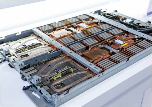
While chillers and pumps generate the cooling capacity, the actual heat transfer occurs at the component level. The most critical piece of hardware in this thermal architecture is the liquid cold plate module. Engineered from premium-grade aluminum alloy, this highly conductive metal component features a complex internal network of micro-channels through which the coolant flows.
The primary advantage of this component is its physical placement. Unlike air cooling, which relies on convective heat transfer across a distance, the cold plate is installed in direct physical contact with the battery cells. To eliminate microscopic air gaps and maximize thermal conductivity, a specialized Thermal Interface Material is applied between the cell surface and the metal plate. This direct conduction pathway allows heat to be drawn away from the battery cells instantly.
The engineering of the plate dictates its effectiveness. Industry-leading designs feature optimized micro-channel flow geometries designed to balance a pressure drop of less than 30kPa with maximum surface area contact. Because the plate maintains continuous, direct contact with the cells, heat is extracted uniformly across the entire surface. If one cell begins to generate more heat due to internal resistance, the cold plate immediately absorbs that excess thermal energy and carries it away in the fluid stream. This ultra-high heat dissipation efficiency makes the formation of hot spots virtually impossible.
Despite its overwhelming thermal superiority, liquid cooling introduces specific engineering challenges that must be addressed to ensure system safety. Inside a battery cabinet, ambient air holds a certain amount of moisture. If the surface temperature of the energy storage liquid cooling plate drops below the dew point of the surrounding air, water vapor will condense into liquid droplets. In a high-voltage electrical environment, pooling water presents a severe risk of short circuits and catastrophic failure.
Modern systems employ sophisticated dew-point control algorithms to eliminate this risk entirely. The control unit continuously monitors both internal ambient temperature and relative humidity to calculate the real-time dew point. It then dynamically adjusts the coolant flow and chiller output to ensure the plate's surface temperature always remains safely above the dew point, while still providing robust cooling to the cells. Many cabinets also integrate active dehumidifiers to keep internal moisture levels exceptionally low.
Beyond condensation, the fear of coolant leaks is a common hesitation among facility operators. To mitigate this, enterprise-grade modules utilize aerospace-level vacuum brazing techniques, robust O-ring seals, and IP67-rated connectors. Cabinets are equipped with highly sensitive leak detection sensors and pressure-drop monitors that instantly shut down the pumps and isolate the system at the first sign of a pressure anomaly.
For organizations evaluating thermal management architectures, the transition to liquid cooling is no longer a futuristic concept. It is a present-day engineering necessity driven by hard data and project economics. While the upfront capital expenditure for a liquid-cooled system may be marginally higher than a traditional air-cooled setup, the total cost of ownership is significantly lower.
When specifying a liquid cooling system for your energy storage project, ensure your vendor meets the following criteria:
Material Quality: Insist on high-grade aluminum alloys with strict flatness tolerances to ensure perfect contact with the Thermal Interface Material.
Flow Optimization: Verify that the internal micro-channels are designed to minimize pressure drop while maximizing turbulent flow for superior heat transfer.
Safety Ratings: Ensure all fluid connectors and manifolds carry an IP67 rating or higher to guarantee leak-free operation over a 10 to 15-year lifespan.
Active Monitoring: The system must include dynamic dew-point tracking and rapid-response pressure sensors.
By eliminating hot spots and maintaining strict temperature uniformity, liquid cooling can extend the operational lifespan of a battery asset by 20% to 30%. Because liquid cooling is highly targeted, the auxiliary power consumption required to run pumps is drastically lower than the energy required to power massive HVAC fans, reducing ongoing operational expenditures.
Implementing a direct-contact liquid architecture now ensures that your infrastructure is prepared for the next generation of high-capacity cells. If you are looking to secure your investment, guarantee safety, and maximize long-term performance, consult with thermal engineering experts. Explore advanced thermal management solutions from RUN Strategy to find the exact liquid cooling architecture that fits your project requirements.
It is a highly conductive metal plate, usually made of premium aluminum or copper, featuring internal micro-channels. Liquid coolant flows through these channels while the plate sits in direct physical contact with battery cells, efficiently absorbing and dissipating heat away from the source before hot spots can form.
By providing rapid, uniform cooling directly at the cell level, the system prevents any single battery cell from reaching the critical temperature thresholds—typically above 130°C—that trigger the uncontrollable chain reaction known as thermal runaway.
Yes. Modern thermal management systems are designed with extreme safety tolerances. They utilize non-conductive coolants, aerospace-grade vacuum brazing, leak detection sensors, and dynamic anti-condensation controls to ensure zero risk of electrical shorts or fluid leaks.
While technically possible in some scenarios, retrofitting is highly complex, labor-intensive, and often cost-prohibitive. It requires replacing rack structures and integrating new plumbing manifolds. It is highly recommended to specify liquid cooling during the initial design and procurement phase of your energy storage project.
Most industrial lithium-ion battery systems operate most safely and efficiently between 15°C and 25°C. Crucially, the temperature difference between individual cells within the same module should never exceed 3°C to 5°C to ensure uniform aging and optimal performance.
By maintaining strict temperature uniformity and preventing the accelerated degradation caused by hot spots, a well-engineered liquid cooling system can extend the overall operational lifespan of a lithium-ion battery asset by 20% to 30% compared to traditional air-cooled systems.
Routine maintenance is surprisingly straightforward. It typically involves visually inspecting manifolds for leaks, checking coolant fluid levels and quality, verifying pump operation, and ensuring the chiller's heat exchangers are free of debris. Enterprise systems feature self-diagnostics that alert operators long before a physical inspection is required.


